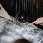
I see that you got the access plate off of the IR compartment. When you put it back on - do not tighten those screws that much. When you strip out the phillips head, they are only removeable by drilling or using a smally cold chisle. When you drill, only remove the head, then you can get to the rest of the screw by using a small vice grip. The nut plates are hard to find now. The screw has a common thread - probably 10/32 pitch.
In the back acess compartment (Behind the IR head, you should find the two connector plugs that attach to the bottome side of the IR head. The four bolts holding the head in place are hex head - 7/32 allenwrench in size. Some times they were all safety wired with the small size safety wire. usually came from the factory that way! We DIDN"T!! Too much of a problem!
If that airframe had the Closed Cycle cooling, then there would also be another plater to the aft of the plate you have in your hand - somewhat siimilar in size and located a bit farther down the right side of the aircraft surface. Inside of that plate you would find the IR compressor motor and behind it - the IR Nitrogen holding tank. If it was upgraded to the TEC - Thermal Cooldown - all that stuff would be gone So - more pictures when you get the access panels opend up - please!?!?!
MA1RV
- Sunday 1 April 2012 21:35
I see that you got the access plate off of the IR compartment. When you put it back on - do not tighten those screws that much. When you strip out the phillips head, they are only removeable by drilling or using a smally cold chisle. When you drill, only remove the head, then you can get to the rest of the screw by using a small vice grip. The nut plates are hard to find now. The screw has a common thread - probably 10/32 pitch.
In the back acess compartment (Behind the IR head, you should find the two connector plugs that attach to the bottome side of the IR head. The four bolts holding the head in place are hex head - 7/32 allenwrench in size. Some times they were all safety wired with the small size safety wire. usually came from the factory that way! We DIDN"T!! Too much of a problem!
If that airframe had the Closed Cycle cooling, then there would also be another plater to the aft of the plate you have in your hand - somewhat siimilar in size and located a bit farther down the right side of the aircraft surface. Inside of that plate you would find the IR compressor motor and behind it - the IR Nitrogen holding tank. If it was upgraded to the TEC - Thermal Cooldown - all that stuff would be gone So - more pictures when you get the access panels opend up - please!?!?!
MA1RV
- Sunday 1 April 2012 21:22
That is the stinger package and the T handle to load the missle or AATs or WSEm on the rail. The handle had to be pulled back while loading, then released after you shoved the missle/AATs/WSEM into place.
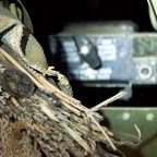
The big bundle of cut wires on the left spells big time headaches. You might need to locate a -24 wiring guide to find the ones you need to get the system to work - even if you are thinking of bypassing alot of connections. I would give you the advice of just running a whole new wire to whatever location is needed. You might want to invest in about 2 miles of 20 guage braided for this project.