IRSTS - Infrared Search and Track System
As a delta-winged aircraft the F-106 control configurations included elevons' instead of horizontal stabilizer and elevators. This made the Six handle extremely well at low speeds as well as high ones, even when operating at or near specified minimums. General flight characteristics of the Six fitted with the supersonic rated external 360 fuel tanks were essentially the same as in 'clean' configuration (no external fuel tanks), except that control at lower speeds was somewhat more demanding. Advantages of the delta wing with its high surface area included excellent performance at high altitudes, and agile turning ability at intermediate and lower altitudes. All possible due to advanced mechanical flight control components.
While the automated aspects of the AFCS, MA-1 and SAGE systems were advanced for there time, so were the mechanicals of the manual flight controls and artificial feel systems on the aircraft. Flight Control Rigging and maintaining was an involved, complex task and included members from numerous shops to include APG (crew chiefs), Hydraulics, Electrics, MA-1, and in fact AFCS even had it's oun AFSC of 325x0A with FC&M specialists.
This is a short of Flight Control Mechanical components included in the flight control system. Technical Order 1F-106A-4 was the bible for flight controls.
• Mixer Assembly
• Elevons
• Artificial Feel Force Cylinder
• Auto trim switches
• HEP Valve - move the main servos, when AFCS engaged
• HRP valves
• Shelly Unit
FlightControlSystem-Testing-590051-1981-BillyMarshall.pdf
F-106 Flight Control Malfunctions
Two CLASS A mishaps in 1981 involving Flight Control malfunctions revealed the need for ADTAC to direct an indepth analysys of the Automatic Flight Control System of every F-106 still flying in the fleet. Any aircraft experiancing flight control malfunctions during any ground operation were to be immedialtely impounded.
The PDF document here are notes made by MSgt Billy Marshall, Superintendent Phase Inspection Docks, 87th Fighter Interceptor Squadron, K.I. Sawyer AFB MI in 1981 on F-106A 59-0051. As the night shift supervisor of Phase, MSgt Marshall was my supervisor and probably had more knoweldge and experiance of the F-106 AFCS system of anyone.
The "brain" of the F-106 was the sophisticated Hughes MA-1 electronic and fire control system. When used in conjunction the SAGE (Semi-Automatic Ground Environment) defense system, the F-106 could actually be fully computer-flown during most of its mission, the pilot only needed for takeoff, landing, or in case of a malfunction with the system. During the automated intercept, the MA-1 would take over control of the plane shortly after takeoff and guide it to the proper altitude and attack position, lock on and fire the F-106 weapons at the intruder aircraft. The pilot using his Tactical Situation Display (TSD), located just below the instrument panel, would observe this entire intercept. The TSD would use map projections and small symbols to represent the intercept mission.
The MA-1 fire control system was initially quite unreliable and was subjected to a lot of in-service modifications in an attempt to fix its chronic problems. The MA-1 system was upgraded 60+ times during the Delta Dart's long service life. In 1960, devices for long-range detection and electronic counter-countermeasures equipment were added, along with the capability for using angle chaff, silent lobing, and pulse-to-pulse frequency techniques. Anti-chaff devices were added in an effort to defeat enemy attempts to confuse the fire control system by dropping bits of radar-reflective strips. The modification programs involved 314 F-106As and were completed by the end of 1963.
The F-106A operated in conjunction with the SAGE, 'Semi-Automatic Ground Environment', (described below) network linked via the Hughes MA-1 fire-control system to the F-106. It operated by plotting the course needed to intercept an enemy aircraft, automatically sighted the target, fired the air-to-air missiles, and then automatically placed the F-106 on the correct course to disengage. The F-106 could actually be fully computer-flown during most of its mission, the pilot being needed only for takeoff, landing, or in case something went wrong with the automation. Flight testing continued until early 1961, with each phase of the test program turning up a whole host of problems which required important engineering changes. Each change had to be defined, engineered, reviewed, and approved for production before modification of aircraft off the assembly line could begin. The Cook-Cragie production policy only made problems worse and by 1960 the Air Defense Command had so many different F-106 configurations out in the field that maintenance support was a nightmare. In September of 1960, due to the numerous modifications to the MA-1 fire control system made during production, a major modification project named "Wild Goose" was initiated to bring the earlier F-106s up to the latest production standard. Early in 1960, ADC could list 63 changes in the F-106A's fire control system and 67 changes in the airframe that would be required to make early F-106s equivalent to the machines currently coming off the production line. Lasting a full year, the program involved roaming AMC field assistance teams supported by ADC maintenance teams working at ADC bases. The 277th and last F-106A was delivered on 20 July 1961.
The production run also included 63 F-106B two-seaters, for a total of 340 aircraft.
In late 1961, Secretary of Defense Robert S. McNamara spoke of reopening the F-106 production line to build another 36 aircraft (rather than the 80 originally budgeted for in FY 1961). However, the ADC had heard so much about the capabilities of the Navy's F4H-1 Phantom two-seat interceptor that it thought that it might be a better idea to purchase some F4H-1s rather than buy additional F-106s. The USAF called for a competition-named Project High Speed-between the F-106 and the Navy's F4H-1 Phantom. It was designed to evaluate the capabilities of these two aircraft to perform similar missions. During the competition, the Phantom's APQ-72 radar was more reliable and had longer detection and lock-on ranges than the MA-1 system of the F-106. However, in many sorties F-106 pilots "shot down" their F4H adversaries in visual range combat situations. In the event, neither aircraft got the nod for additional ADC interceptor orders, and in December of 1961, the USAF announced that the F4H/F-110 would be acquired for the Tactical Air Command and that ADC would get no new interceptors. Even after all aircraft had been delivered, reliability problems continued to plague the MA-1 and ASQ-25 systems. Throughout its long service life, the F-106A was continually upgraded and improved to correct these problems. The "Broad Jump" modification program started in late 1960 was a long-term program for general improvements in the F-106A. This program was carried out by people at the Sacramento Air Material Area, and it extended through early 1963. Among the changes introduced by this program was the fitting of an infrared search-and-track sight that could operate at low altitudes and against varied backgrounds. The unit retracted into a fairing in front of the cockpit.
In 1962, F-106As were fitted with a Sheaffer Spring Hook arrester system designed to engage wires at the end of the runway in the event of an landing overshoot, becoming the first USAF combat aircraft to be so equipped. The F-106A was never intended for carrier-based operations. The F-106 had to be grounded again on 26 September 1961 to make repairs to the fuel system which had caused two crashes. This order did not affect the F-106s that were on alert with ADC, but it did affect those used for training and transition flying. In response to this grounding, the "Dart Board" retrofit and modification program took place in 1961-62. This program finally fixed the problem with flame-outs from fuel starvation which had affected earlier Delta Darts. A thermal flash blindness protection hood was also fitted. Perhaps the most significant of these changes, however, was the revision of the ejection system.
as described by Marvin “Marv” Donnelly
The first 080 unit that “6” [F-106] had was called a DVST. This stood for Direct View storage Tube. Most prominent identifying characteristic was that the scope face – when lit and operating – was a blue or bluish in color. Most were very bright in a full on operation. The scope face was somewhat slanted to cut down the glare for the pilot. The top of the scope was mostly just a big round tube with nothing attached. The forward window had a rigid panel mounted in the “V” formed by the two forward cockpit windows. Only things mounted up in that area were the 169, the hanging optical site and a standby compass. This configuration was used up through the 1970 time frame.
Back in 1969 or so the new MMST came into the aircraft. The Multi-Mode Storage Tube as it was called was a pretty big improvement for the pilot. The old DVST had controls for brightness and focus, but the new MMST also included a contrast adjustment and a capability to change the screen from all white (Think bright!) to a reverse screen of all black. Added to this config was the new 149 unit. The 149 was the 8mm video tape recorder to record what was displayed on the 080 screen during the pilot’s attempts to lock-on and make a missile run. The old 149 unit was mounted on the 05 door and had to be changed each time the aircraft flew a mission. To do this the MA-1 person would open the 05 door and remove the old film pack and replace with a fresh one. By putting the new 149 up and attached to the MMST, the changing of a film pack was great improved. The new MMST had the 149 mounted on top of the scope tube and received the display info via a reflective image from the angled scope face plate. The image for the pilot was only slightly dimmed as the image transferred through the scope face lens. The vision splitter panel was modified and cut out to accommodate the new 080 with 149 unit attached.
The latter life time of the “6” saw the 080 modified again, this was about the 1982 83 time frame. At this time the “6” was gaining the Vulcan gun mount. The vertical instrument “A” models were all selected for the gun. No round instrument models were given the gun system because of the analog nature of the instrumentation. So – the 080 was modified by changing the 149 unit and making it fit farther forward on the 080, and the HUD – Heads Up Display – had a large combining glass added. The combining glass was installed on top of the 080 with another video splitting mirror inside the scope face. That way the 149 camera got the display video and the gun selection displays could be seen on the combing glass – in front of the pilot. The pilot would use the aim points displayed on that combining glass and the real visual image of what they were following through the forward window. This system actually worked very well!
The Vertical instrument “A” models had the 080 with the HUD installed. The other aircraft had the newer 149 unit installed but no HUD. No real problem – just had to make sure the HUD Combining glass was installed as needed. The other two units that were modified for the gun mod aircraft were the 083 (Flight Control Stick) and the 305 unit (RADAR range/IR selector panel). On the armament selector panel the gun was elected by going to Special Weapon. This was because when armed with the gun, the MB-1 Special Weapon rack was removed and the gun pod installed in its place.
The SAGE was a real-time, computer based command and control system designed in the late 1950's and fully functional and deployed by 1963 and used up though 1983. This automated control system was used by NORAD for tracking and intercepting enemy bomber aircraft. In the later versions the system could automatically direct aircraft to an interception by sending instructions directly to the aircraft's autopilot.
The system consisted of 24 Directional Centers around the United States as well as 3 Combat Centers. Data was collected at each of the directional centers from over 100 different sources such as radar, human volunteers and aircraft sightings. This information was collated and forwarded via telephone communication lines to one of the three combat centers. The information was interpreted by the computer and displayed on something totally revolutionary for that time period: a cathode ray tube display screen. The display, while similar to a radar screen, was extremely versatile. The operator of the terminal could pull up past positions of aircraft or missiles, as well as project future locations. In addition, the system used another feature far in advance of its time: a light gun. The gun was used by the operators to point at an aircraft on the screen, and the computer would respond by displaying related identification information about that aircraft. The system has the dubious distinction of holding the record for the world's largest (physical size) computer ever created.
By the time the SAGE system was fully deployed, it was obsolete, no match for the speed of new ICBMs. SAGE was never designed to counter a space or missile threat. It was designed to counter the air threat. SAGE was operating long after the ICBM threat was recognized. Maybe it would have been closed due to ICBMs had the Soviets gotten rid of its manned bomber force and maintained only the Strategic Rocket Forces. SAGE was eventually closed because the bomber threat diminished, thus the mission became airspace sovereignty not defense. Some SAGE centers continued to operate until 1983, more than 20 years after its technology was obsolete and its mission rendered militarily insignificant by the ICBM. As a final irony, in the last years of its use, replacement vacuum tubes had to be purchased from Soviet-bloc countries where they were still being widely manufactured. Nevertheless, SAGE was extremely important and its many technical advances in on-line systems, interactive and real-time computing including modems for communication between sites over telephone lines, networking, light guns, graphical displays, and reliable magnetic core memory. The technology led to Sabre, the airline reservation system still in use today.
The SAGE system and its development is generally considered to be one of the most advanced and successful large computer systems ever developed. According to Jim Ray, "SAGE was one of the engineering marvels of the century. In fact if it looked better, it might have been ranked with the Eiffel Tower, the Saturn Rocket or the Golden Gate Bridge for engineering accomplishment. It also pioneered some of the most of the important technology used to facilitate internet processing today: i.e., the modem, the mouse [light gun], multi-tasking, array processing, computer learning, fault detection, magnetic memory, and interactive computer graphics. Most important, it worked well enough for each center to coordinate about 100 operators , track 300 simultaneous flights, control numerous sorties against a maneuvering radar-jamming 'enemy', and coordinate 'friendly' NIKE and Bomarc defenses." IBM built the SAGE hardware based on the Whirlwind computer design at MIT. The software was written by The Rand Corporation and the System Development Corporation (SDC) and employed about 20% of the world's programmers at the peak of the project. When it was complete, the 250,000 lines of code was the most complex piece of software in existence.
Each of the 27 SAGE installations had two separate computers, the second serving as a "hot standby" in case the active computer failed. With this backup, availability was an unprecedented 99.6%, when many other computers from that era would fail every few hours. The computer weighed 300 tons and typically occupied one floor of a huge windowless 4-story concrete blockhouse. On another floor, dozens of Air Force operators watched their display screens and waited for signs of enemy activity.
Some SAGE centers continued to operate until 1983, more than 20 years after its technology was obsolete and its mission rendered militarily insignificant by the ICBM. As a final irony, in the last years of its use, replacement vacuum tubes had to be purchased from Soviet-bloc countries where they were still being widely manufactured.
The F-106A Delta Dart operated in conjunction with the SAGE (Semi-Automatic Ground Environment) network linked via the Hughes MA-1 fire-control system to the F-106. It operated by plotting the course needed to intercept an enemy aircraft, automatically sighted the target, fired the air-to-air missiles, and then automatically placed the F-106 on the correct course to disengage. The F-106 could actually be computer-flown during most of its mission, the pilot being needed only for takeoff, landing, or in case something went wrong with the automation.
The primary means of communication between SAGE and the F-106 was
accomplished using Time Division Data Link (TDDL), intent being to provide non-verbal commands for vectoring the
aircraft towards a successful intercept. Signals from the SAGE AN/GKA-5
transmitter were received by the F-106 data link receiver; either an AN/ARR-60
or AN/ARR-61. SAGE provided two modes of control for interceptor command
and navigation: Close Control (CC) and Modified Close Control (MCC). The
SAGE transmission would dictate which of the two modes would be dominant in a
given scenario i.e. SAGE would dictate if the
intercept would be conducted under CC or MCC.
Close Control (CC) - The primary mode of the data link was Close
Control. In this mode the SAGE transmitter would send an encoded message
to the aircraft Data Link receiver which would check it for validity and proper
aircraft address before sending the information on to the
F-106 Delta Dart's MA-1
computer. The MA-1 computer would in turn use this information to send
commands for mach, altitude and heading to the Automatic Flight Control System (AFSC)
and cockpit displays for vectoring the interceptor towards the target.
While the AFSC could automatically accomplish the altitude and heading commands,
the pilot needed to manually adjust the throttle to achieve the command speed.
Modified Close Control (MCC) - When an F-106 was paired up with a
target, in addition to the altitude, speed and heading CC commands for the
interceptor, SAGE would also send MCC messages that contained extensive target
information. The Data Link receiver would validate the messages and pass
them on to the MA-1 computer. The MA-1 computer would use this information
to calculate the tactics required and send the corresponding speed, altitude and
heading commands to the cockpit displays and AFSC. Two types of MCC
messages were transmitted by SAGE: MCC-Region Origin (MCC TACAN) and MCC-Interceptor
(MCC-NO TACAN).
- In MCC Region Origin, target X and Y coordinates were referenced with respect to the SAGE origin
- In MCC-Interceptor, target position was referenced with respect to the interceptor.
The default mode was MCC-Region Origin.
MCC-Interceptor usually had to be requested by the pilot except when MCC
messages where sent as backup messages during the CC dominant mode.
In the Cockpit - TDDL interaction between SAGE and the F-106 was
controlled in the cockpit using the Data Link Converter Receiver Control Panel
located on the right console. The pilot could select a SAGE frequency
using one of 26 preset channels, or manually insert a four digit channel.
Using the Address Select switch, the pilot could select one of 32 aircraft
addresses that would be compared to the aircraft address embedded in the SAGE
signal as one of the means for validating the transmission. The receiver
also accommodated back-up data link voice communication.
The Display/Automatic Mode Selector Switch on the main instrument panel
determined what data link information was displayed and how intercept tactics
would be executed. There were two positions for the switch: MAX RANGE and
DL MIN TIME. Each had different meanings depending on which data link mode
was dominant (CC or MCC). For example if by SAGE command the dominant mode
was CC, then there was no difference between the MAX RANGE and DL MIN TIME
settings because SAGE was performing and issuing the interceptor guidance
calculations. However, if the dominant mode was MCC, the position of the
switch governed the profile and tactics commanded by the MA-1 computer to
approach and attack the target. Typical tactics included:
DC-1: McGuire AFB, NJ
DC-2: Stewart AFB, NY
DC-3 / CC-1: Hancock Field, NY
DC-4: Fort Lee AFS, VA
DC-5: Topsham AFS, ME (blockhouse demolished)
DC-6: Fort Custer, MI
DC-7 / CC-2: Truax Field, WI
DC-8: Richards-Gebaur AFB, MO
DC-9: Gunter AFB, AL
DC-10: Duluth IAP, MN
DC-11: Grand Forks AFB, ND
DC-12 / CC-3: McChord AFB, WA
DC-13: Adair AFS, OR
DC-14: K. I. Sawyer AFB, MI
DC-15: Larson AFB, WA
DC-16: Stead AFB, NV
DC-17: Norton AFB, CA
DC-18: Beale AFB, CA
DC-19 / CC-4*: Minot AFB, ND (* CC-4 blockhouse built, but AN/FSQ-8 never installed)
DC-20: Malmstrom AFB, MT
DC-21: Luke AFB, AZ
DC-22: Sioux City AFS, IA
SCC-5: Hamilton AFB, CA
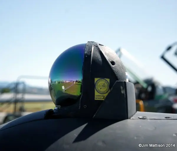
As an F-106 weapons instructor for many years at the USAF Interceptor Weapons School, we taught squadron-level weapons instructors the finer points of employing the weapons on the Six, I am here to tell you that the IRSTS, (Infrared Search and Track System) gave the Six a tremendous advantage in all combat environments. It consisted of a dome, mounted just at the forward base of the windscreen, which the pilot could extend or retract with a push of a switch on the inside of the left control stick. The dome had an infrared seeker inside that could detect and or track any IR source (the sun, any airplane recip, turbine or rocket engine, etc., etc) It would then tell the MA-1 fire control system the azimuth and elevation of the IR source. The pilot would see a spiked dot on the radar screen at the az and el of the target and would hear a distinctive tome; the tone and the spike would increase as more of the IR source was received (i.e., when you got closer). You could slave the IRSTS to the radar, in which case it would confirm a radar lockon to an IR emitting target (i.e., not chaff or ECM) or you could slave the radar to the IRSTS, so with an IR (Angle-only lockon) the radar (in sweep or track) would “see” the radar return and give the range to whatever the IR was tracking, This was especially critical when looking down at very low altitude to find a target hiding in ground clutter and also dropping chaff or blinding the radar with barrage jamming. The IRSTS was also the ONLY way to go against high altitude supersonic targets. The IRSTS would get a very strong return at as much as 180 miles away; long before the radar would see the target; then you could slave the radar to the IR and it would get the longest possible radar contact range. This was especially critical on high-closure rate front attacks (Mach 2 to Mach 3 plus combined closure rates). We were very successful at shooting down BOMARCs as drones in this environment. In short, the IRSTS IN COMBINATION WITH the radar made the Six DEADLY.
At very low altitude, when the target was lost on radar in ground clutter and/or ECM, we taught the students to do IR ANGLE-RANGING: fly down until the IR source was level then climb 1000 ft. When the new down-look angle reached 20 degrees the target was within missile range. We fired IR missiles without ever seeing the targets visually or on radar; our students had to do it from the back seat of a B Model
UNDER THE BAG
The IRSTS (IR Search and Track System) was extremely useful. Our MA-1 radar system was NOT Doppler and that meant that low-flying targets could "hide" in ground clutter. But the IRSTS would detect and track them even if their engine(s) put out the slightest amount of heat. Then we could slave the radar to the IR and be assured that the radar was looking exactly at what the IR was tracking and then we could tune the radar so it would see the target regardless of the ground clutter, and we could successfully launch missiles or the Genie. The IRSTS was also invaluable at high altitude on frontal attacks against high flying hypersonic targets like the Soviet Foxbat. We simulated actually shooting down that kind of target by successfully engaging BOMARC missiles flying above Mach 2.0 and above 80,000 ft. The IRSTS would "see" the BOMARC long before the radar would as far as 180 miles away and we would slave the radar to the IR so it could see the radar return in time for us to lock the radar (just a few seconds before launch) with closure rates in excess of Mach 3.5. I loved the IRSTS.
-- Mark Foxwell, Col USAF (Ret)
USAF Interceptor Weapons School Instructor and Commander
IRSTS - Infrared Search and Track System