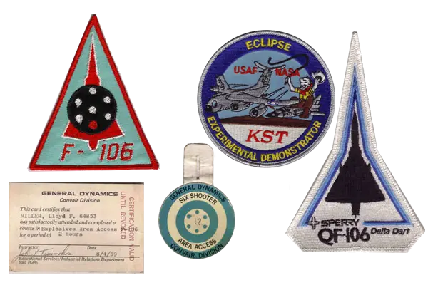
Some of Lloyd Miller's patches and a Convair ID Card
Edwards AFB, CA Program
On 6 July 2011 we received an e-mail from Lloyd Miller, a Convair Engineer who worked the F-106 Flight Development Program at Edwards AFB CA from the start of the program in the late 1950s. Lloyd offered photos and stories of some of his experiences with the F-106 program we want to share below.
He joined Convair and was assigned to the Hydraulics Design Group where he was put in charge of the hydraulic system component installations in the prototype aircraft. He went with the prototype aircraft to Edwards to represent the design group and soon after, transferred to the Flight Test Group there. He was the Control Engineer on F-106A 56-0467 that was used for the world speed record runs at Edwards AFB with an official record speed of 1525.95 mph, Mach 2.42 (read about the speed record). Side note: during the speed run trials leading up to the actual run, it was discovered the reason for the lack of performance of the aircraft was due to a fault in the afterburner fuel control schedule which limited fuel flow (thrust) in AB at altitude. As a result, Convair recovered the performance penalty assessed by the AF. Sometime during the service time of the aircraft, the engine trim was reduced to extend engine life. Lloyd was also involved in the 'aftermarket' air-to-air refueling installation and test (more about the IFR Refueling), and the "Six Shooter" M61A1 20mm cannon installation and test (more about the M61A1 on the Six). Lloyd and his teams were a huge part of great aircraft. He stated "It was a great bird and I am proud to have been part of a great test crew and organization to help put it in service". Below are some patches from Lloyd's box of memorabilia. Lloyd mentioned in an email to me that "the KST F-106 towing demonstrator and the QF-106 development programs came to the company I was working for in Mojave after my time on the F-106 program. We didn’t get to do the production program. The F-106 Six Shooter patch you see was given to those of us that worked on the program. I’m not sure if it was ever issued to any organizational unit".
For those that might be interested in the F-106 development flight test program at Edwards AFB, this will provide a one person perspective of a small part of the action. Speaking of action, it is usual in some parts of the military to write up an “After Action Report” which usually includes a section titled “Terrain Sketch” which provides background information useful in understanding the actual “Action.” This background is as follows:
Fresh out of school, I was hired by Convair about the time the F-106 was beginning to take shape in the preliminary design group. I was assigned to the Hydraulic Design Group and was the group interface with the Preliminary Design Group and later with the various design group sections as the design progressed. The design matured and wood mock-up was constructed, followed by metal mock-up where the placement of system components was proved. I also designed some minor parts for the aircraft at that time as I followed the assembly of the two prototypes, 451 and 452.
When 451 was trucked to EAFB, George McHenry and I were assigned to provide support the flight test group on any hydraulic system problems that might arise during the initial flight tests. During that time, 452 arrived and after working with the members of the flight test group and the aircraft, I realized I was ‘hooked’ on the flight test action and transferred to the group where I remained for the duration of the F-106 EAFB program and George returned to the design group. My job title was “Flight Test Control Engineer” and as such, was responsible to make sure the aircraft configuration including instrumentation was as required by the test to be flown. This also included coordinating aircraft operational activities, modifications and repairs. I also was involved several F-106 “after market” mods and test including the Six Shooter, Clear Top Canopy, and the Aircraft Structural Integrity Program (ASIP).
A/C 451 was used as the main systems evaluator and 452 was the powerplant and performance aircraft and were each instrumented accordingly. I was assigned to work with C. B. “Blic” Wells on 452 and later when the production version (459) arrived. I should note at this point, the external difference between the prototypes and the production aircraft was mainly the angle the inlet was set at. The prototypes were square with the aircraft reference line and the production was set at -2 degrees.
After some months, “CB” transferred to Holloman AFB to help with the weapons integration testing part of the program which was just beginning, and I stayed with 459. “CB,” as he was known by all, was my friend and mentor in the F-106 flight test business.
The other production aircraft in the test program were assigned and instrumented to test other systems, such as heating and vent, flight loads, etc. I think there were about six aircraft on site at any given time. Also, I believe the F-106 program was the last program where the contractor and the Air Force had separate and mirror flight test groups and aircraft. When the contractor completed a contract test point, the AF group would verify it with their aircraft. The mirror aircraft of 459 was 467.
Some of the tests that were done on 459 included flying several different engine cooling shroud exhaust nozzle shapes to minimize aerodynamic drag in an effort to achieve contract performance guarantees and explore the speed related yaw phenomenon which no other aircraft had experienced. A/C 459 was performing below guarantee speed and Convair was facing a contract penalty for it. Of course Convair accused Pratt and Whitney of insufficient thrust and P&W said they were good and the problem was with the aircraft drag.
One of the records to be attempted at the same time as the speed run was the zoom climb. This would involve accelerating to Vmax and then basically trading kinetic energy to altitude by a rapid climb to maximum attainable altitude. One of the Convair test pilots, Chuck Myers, believed the F-106 could also capture the zoom climb record and was allowed to try. I don’t remember for sure which aircraft was used but since the aircraft was going to be flown at such a high altitude some special attention had to be paid for the pilot at that altitude (full pressure suit) and radio equipment. All the test aircraft at the time were equipped with ARC-34 radios which were old tube type, even for then, and were not designed to be operated in near space low pressure environment. My assignment was to fix the radio so it would operate at that expected high altitude. Since the radio had to be cooled as well as pressurized, I found that two CSD shipping cans welded together end to end with the bases removed would make an acceptable pressure vessel and a quantity of crushed dry ice would provide the cooling. I had two fuel tank relief valves (redundancy for over pressure safety) installed in the opposite removable end of the assembly. It bench tested ok and was installed in the missile bay.
The run was made and all worked ok except the F-106 was not as heavy as the F-4 which meant less KE available. The F-4 got the record. I think Chuck said he saw 84,000 feet on his altimeter and 106KIS going over the top, at which point the aircraft was on a ballistic trajectory.
I do recall the side stick controller test (it’s been so long since and anything beyond overnight is subject to memory loss.) I was not involved in the test, but I presume our chief pilot at the time, Dick Johnson, probably was. I believe he was the person that conceived the original idea of the two headed control stick so the pilot could control the situation display with one side while flying the plane with the other. However, I suspect (my personal opinion) the center control stick placement somewhat blocked the view of the situation screen which was located low in the center panel and so the side stick controller was tried.

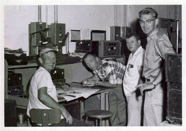
Lloyd Miller (plaid shirt) looking at a mechanical throttle rate damper
I think the main problem implementing it may have been getting a reliable and repeatable null and scaled proportional output. The flight controls on the F-106 were all mechanical input to the HEP and HERP packages with only autopilot and pilot assist overlaying the mechanical input. If my fading memory serves correctly, I think the side stick output was from a strain gage network and not mechanical which meant only force and no pilot discernable displacement of the side stick resulted from pilot input. Even if this approach would have worked it would have meant a significant pilot familiarization issue to resolve. All the Convair test pilots were either test pilot school trained and/or had lots of valuable flight experience so you could expect the best result from the test by any of them. Anyway, the idea was finally abandoned. Without the benefit of a modern day flight control computer to help manage things you can imagine the problems and the uncertainty of a suitable solution from this approach.
Additional to the write-up: One of the problems encountered with the engine installation was if the throttle was moved too rapidly toward idle while at high speed, there would be at least one compressor stall. One of the solutions tried, with limited success, I think, was a mechanical throttle rate damper which was designed to permit a reduction in throttle position at a rate slow enough to prevent compressor stalls. The initial tests with it installed were disappointing, to say the least, and I undertook an internal inspection of the unit on site to see if there was anything obvious that was preventing it from doing its job. The second picture is of me with the unit with an inspector and lab techs looking on to make sure I didn’t break anything. Nothing obvious was discovered and I suspect the compressor stall problem may have been solved another way, but I don’t recall how.
Also, speaking of compressor stalls, Fitz was on a high speed flight attempt in either 56-0452 or 56-0459 early in the program (but after “CB” had moved to HAFB) when he got a compressor stall backing off of the point. As per plan, an immediate return to base was made and a thorough post flight inspection, especially of the inlet and variable ramp system was conducted. The ramp system was designed to modulate the inlet air flow to the engine for optimum performance. The ramp was in three sections; the first section front was hinged at the back of the inlet boundary layer plow and the front of the second section was hinged to the back of the first. The third section was held in relation to the second by sliding joints and hinged at the aft end to the inlet duct. Hydraulic motor driven screw jacks would move the second in and out as required and the variable gap between the aft end of the second panel and the front end of the third panel was covered by a heavy, 1/8 inch or so thick fairing, which was secured by I think by two or three rows of rivets. After the flight, it was discovered that both of the fairings had been blown out of the intake duct and left traces in the fuselage paint almost to the radome bulkhead! Miraculously, both fairings had been blown out of the inlet duct by the compressor stall at Mach 2 and aside from the paint scuffs never touched any other part of the aircraft. This had occurred coming off a Mach 2 run so we got a worst case test point with no other evidence of damage. I believe it was the next day we got a directive from San Diego to remove the fairings from all the other test aircraft.
I think this F-106B was 57-2507 and crew prior to it being burned in a nose wheel shimmy test. The pilot is Jim Stuart. The project boss was George Miller in front of the ladder and I am next on his left. 2507 was heavily damaged during a taxi test to gather information on the cause of nose wheel shimmy which happened on some aircraft. There was serious concern for brake/tire overheat during the test, knowing that a blown tire on a high speed taxi run would result in a wheel disintegration followed by brake disk segments puncturing the fuel tank and fire. (All of that except for the fire part had occurred earlier on either 452 or 459 when Fitz had a tire blow on a take off roll and he coasted into the dirt overrun at the end of the runway).

F-106B 57-2507 with the crew. Lloyd is on the back row, 3rd from the right.
To minimize the risk, brake temp instrumentation was added in the cockpit and we were limited to a single run without approval from the program manager in San Diego. The first run was made which was into the wind so that minimum braking would be required at the end of the run. At the end of the run, the brake temp gages hardly moved and a physical check of the tires was made and they were barely warm to the touch. We received an ok to do a second run which was down wind and toward the lakebed.;
The wind was blowing about 25-30 kts. (about average for EAFB) and we were following in our radio car. Jim started the run with us trying to keep up but 2507 quickly disappeared from view down the runway. A few seconds into the run the tower called “2507 you are on fire” and Jim acknowledged with a very calm “roger.” We could soon see the smoke and flames and the dust from the fire trucks that had arrived at the scene ahead of us! We found Jim walking back toward the runway and picked him up. He said he had no trouble with the fire because when the aircraft went off the end of the runway onto the lakebed, the drag from the wheel-less left main gear in the dirt had turned the aircraft so that it was pointed into the wind and Jim had just jumped over the side and the flames were being blown the other direction. He said the most fear he had of the whole event was being run over by a fire truck because when they came off the end of the runway onto the lakebed, their dust blew ahead of them and Jim couldn’t tell where they were in the dust cloud. 2507 was later trucked back to San Diego and repaired. Like most, if not all of the early test aircraft (2507 was the first B model), it had the early Case 14 wing shape, I think it was, and so during the repair it got upgraded wings which I think were identified as Case 20.
The other picture is of one of the after market mod/test aircraft F-106A 57-2502 and crew. The aircraft is a production model with the IR ball fairing just in front of the cockpit windscreen. It is the flight loads portion of the Aircraft Structural Integrity Program (ASIP). Most of the flights were flown at Eglin AFB F-106 facility because that location had the variety of pilot skills required in one handy location. The other part of the program involved an instrumented aircraft in a ground based fatigue test to destruction. The F-106 performed so well in that part—it survived well beyond the required cycles and they basically grew so tired of running the test—that failure was finally induced by cutting wing spars.

F-106A 57-2502 Aircraft Structural Integrity Program (ASIP). Lloyd is on the left.
The F-106 with its Scotch Weld fuel tank process produced a very strong wing. The original design life of the aircraft was 4000 hours based on design operational load/fatigue factors. The aircraft fleet was nearing that limit and faced removal from service. This program was to determine the flight loads based on more realistic operational use. It was instrumented to measure flight loads produced when flown by different skill level pilots on a set series of maneuvers.
I’m at the left end in the picture, Howard Auten our Chief Pilot at the time (he was also the test pilot on the Six Shooter Program) is fourth in (hands in pockets), and Ed Emerson, another Convair pilot is fourth in from the right. The original design life of the aircraft was 4000 hours based on design operational stress factors. The aircraft were nearing that limit and faced removal from service. This program was to determine the flight loads based on more realistic operational use. It was instrumented to measure flight loads produced when flown by different skill level pilots on a set series of maneuvers.
My involvement in the gun program was more on the hardware integration and testing rather than on tactical capability or performance. Probably the best source on that part would be from pilots who were trained in Air Combat Tactics. What I know about the capabilities is second or third hand but I can tell you what I remember about it.
I’m not sure where the idea originated to install a gun in the aircraft but I think it was a good one because in ACT its all about maneuverability and the 6 was arguably the best at the time in that category. The 6 was originally designed to be an interceptor with improved performance and mission capability over the F-102 and others of that roll. As such, it was originally intended to deal with the threat of an attack by Russian bombers and be based at strategic locations on the CONUS. As time went on, the ADC roll was expanded to include the capability to engage in ACT, which required a gun for close encounters. Missiles, like a rifle, are best at long range but there are times when a pistol works best when the enemy is close.
The M61-A1 gun system had been successfully integrated into the F-4 and it was decided to not re-invent the wheel with a drastically different arrangement, so what was installed was nearly identical to the one in the F-4. The F-4 initially had problems with gun gas ingestion caused engine flameouts which were solved with a muzzle design which was adapted to the 6 as well, although the gun placement in the forward missile bay so there was no gas ingestion problem but would help mitigate the muzzle blast pressure pulses on the missile bay doors. We had heard that the F-4 also had a trim offset that was applied whenever the gun was fired to compensate for the asymmetric recoil force which was around 7,000 a pound average and we anticipated having to do the same if required. However, with the gun placement close to the center of gravity on the 6 along with the inherent stability of the aircraft, no such trim feature was required, at least as we tested it.
Since the gun line of fire was on the aircraft centerline and the nose landing gear was in the way for ground firing, a yoke was designed to support the aircraft nose using two jacks. This allowed a clear line of sight for boresighting and shooting. The aircraft was supported on jacks and securely tied down to prevent movement which would affect the shot group. The main landing gear was left extended. I think the target had something of a cross in the center, but the gun boresight point was somewhere in the upper right quadrant of the target and was reflected in the boresight kit. This was to compensate for the gun dynamics during the firing, which included the tangential acceleration imparted on the bullet by the barrel spin, range to the target and other factors. Anyway, that’s the way we boresighted and tested it. At least one ground firing test was conducted with the engine running. I’m not sure, but I think the canopy was removed for emergency egress for the pilot who squeezed the trigger in the cockpit.
The flight test firings were as I mentioned before and were uneventful except for the beef up of the missile bay door skins ahead of the muzzle and a request by the AF to change the gun muzzle clamp to spread the shot pattern out some (the shot pattern was so tight with the original barrel clamp that it was easy for the pilot to miss a target).
The clear top canopy mod was separate from the gun mod but was part of the required configuration to allow the pilot to view a target directly above, where the original canopy had a wide structural member there separating the separate side panels and blocking the view.
Along about this time, the Navy was operating their “top gun” school using their F-4’s and we heard that some 6 pilots and planes were cycled through for practice and experience. This was something quite different from flying intercept missions for the pilots of the 6. What was told was interesting in that the first day the F-4’s beat up the 6’s pretty bad, the second day it was about even and by the third day the superiority of the 6 and the pilots adapting in that role was clearly demonstrated. We also heard it was somewhat of a frustration for the Navy top gun guys to be beat by the AF. All that is hearsay, but I like to think it’s true. The reason for thinking that is later on when the Viet Nam war was winding down and some of the returning pilots who had flown F-4’s and F-105’s were cycled through F-106 familiarization flights at Eglin AFB where the 6’s were based at the time, the aircraft receive rave reviews. We were there for flight loads data gathering for the Aircraft Structural Integrity program and got acquainted with the CO of the unit. During our visit, the CO told how almost without exception, after the familiarization flight in the 6 the very enthusiastic comment was “where has this aircraft been.” The F-106 had been designed for the Air Defense Command who had a more limited requirement for numbers of aircraft. No telling what the historical story would have been if there had been a TAC version as well. Somewhere in my stuff I have a “Six Shooter” patch which those of us who worked on the program received. I’m not sure if it was company or AF issue but I suspect the latter. If I can find it, I’ll scan it and email it to you if you like.
Going back to the original mission driven design requirements, the 6 had no in-flight refueling capability. The addition of this capability was added sometime after the development flight test program began at EAFB, I think. I remember the Program Manager, George Miller (no relation), had to schedule IFR tanker support something like six months in advance because of the high demand for tankers at the time. This was before the IFR mod was even designed. I’m not sure which Convair pilot flew the initial shakedown flight, probably Jim Stuart or James Fitzpatrick. During the flight, one of the test points was to open the slipway door at various speeds to measure any performance change. The first stabilized speed test point was set and when the pilot reported something like “well that’s interesting” (not a good professional statement, but clearly described his observation.) We asked what he meant and he reported that when he opened the slipway door the speed immediately increased abut 2 Kts. I immediately realized the cause for the increase was due to increased thrust due to engine bleed for fuel tank pressurization being shut off in anticipation of fuel transfer from the tanker and we advised him about the cause. One of the test points was to verify the proper disengagement from the tanker refueling boom when it reached its telescoping limit. On that flight, the plan was to gradually approach the boom extend limit by slowly reducing power and let the roller locks on the nozzle allow disengagement. What happened was the pilot gradually reduced power all the way to idle and the drag was so low that the 6 was being towed by the tanker. That was an extra data point (no charge.)
This rough hand plot probably won’t make much sense to anyone but we noticed early in the program that there was some anomaly with the variable inlet ramp system. Mechanically it was fine but in looking at compressor stall data we saw that there could be two different ramp angles for the same duct mach depending on flight conditions when the ramp scheduler began to work. Apparently, the duct mach probe location was such that duct airflow/turbulence/boundary layer would be on one side or the other of the probe and the scheduler worked with that input.

Lloyd's notes on some vari-ramp anomolties
If I remember correctly, the probe total pressures were teed together in a shuttle valve and the controller received the highest pressure. If the highest pressure probe input shifted to the other duct in the bifurcated inlet, that could have had an effect on how the ramps were scheduled. We tested at least one probe position relocation or configuration but I’m not sure what, if anything was ever done to resolve the anomaly.
The plot traces ramp angle vs. aircraft airspeed vs. duct mach. The left scale, I believe are the two different ramp angles possible for the solution. The lower curve traces duct mach starting at the run acceleration and goes up on schedule as the aircraft accelerates. At about Mach 1.8 the steeper slope controller schedule was switched on by the pilot and the duct mach continues up to a point where it remains flat on out to the end of the run. As the aircraft decelerates, the duct mach remains flat down to around Mach 1.8 where the pilot switches the controller back to the original schedule. Both the controller schedules were linear. The faint lines connecting the duct mach trace those data points as the aircraft speed increased and those points as the aircraft speed decreased. The duct mach stayed flat at the high speed end. The curl in the duct mach curve I believe was the steeper slope schedule prior to the switchover from the original design schedule.
The first twelve aircraft were temporarily designated JF-106A for flight tests, but a total of thirty-seven, including the first two aircraft, were used for flight test development. In mid-1957, the F-106A was given the popular name "Delta Dart". Originally, the Air Force had planned to acquire 1000 Delta Darts to equip forty plus Air Defense Command (ADC) squadrons. However, by 1957 the delays in the F-106 program and the problems with the engine and fire control system had resulted in the necessity of a stop-gap measure of ordering other interceptors such as the McDonnell F-101B Voodoo, and the F-106 lost some of its urgent priority. For a while, serious consideration was given to canceling the entire F-106 program, or else redesigning the aircraft as a long-range interceptor. Although the F-106 survived intact, shortages of funds caused a drastic cutback in the number of F-106As on order. By September 1958 the total order of F-106 interceptors had been cut by a factor of three, enabling only fourteen squadrons and a training unit to be equipped. As a result, only 260 more F-106As were ordered. Since the cutback was so drastic, a decision was made in August of 1959 to convert all of the existing 35 F-106A test aircraft to operational status (Model 8-24 standards) and turn them over to the interceptor squadrons. In September of 1958, an early F-106A (serial number 57-0235) was allocated to Ames Research Center at Moffett Field in California for tests of the MA-1 fire control system. On 30 May 1959, the first F-106As were delivered to the Air Defense Command's 539th FIS at McGuire AFB in New Jersey, replacing the F-86L, however, the first "operational unit" was the 498th Fighter Interceptor Squadron at Geiger AFB in Washington. This was five years later than originally planned, and even then, numerous problems kept the Delta Dart from being declared fully operational until 31 October 1959. The remaining 13 squadrons were re-equipped with the F-106A by the end of 1960. On 15 December 1959, Delta Dart 56-467, flown by Major Joseph W. Rogers, set a world's absolute speed record of 1525.96 mph at 40,500 feet, which beat the previous record of 1483.83 mph, set by Georgiy Mossolov in a Soviet Ye-6/3 on 31 October that same year. Initial operational deployment turned up all sorts of problems; generator defects, fuel-flow deficiencies, particularly acute in cold weather, and fuel-combustion-starter malfunctions. In December of 1959, after a canopy had been accidentally jettisoned in flight, all F-106s were temporarily grounded until the problem could be fixed.